2015-03-02 21:47:19 : Updating layout for new blocks.
»
Find 3a8c3faf3cf2ac8144b1050f4c387551018b567b on GitHub.
Updating layout for new blocks.
date: 2013-04-02 12:19:50
thumbnail: sparkfun-synth.jpg
---
{+{% block post %}+}
*This is a compendium of resources assembled for a workshop over the weekend of April 6 and 7 at SparkFun Electronics in Boulder, Colorado.*


@@ -169,3 +170,4 @@ April 6 & 7 has come and gone, and people put together many lovely things. Here'
{{ macros.render_figure('<a href="http://www.flickr.com/photos/samjacoby/8632169749/" title="Drawing the Electric Synth by s_jacoby, on Flickr"><img src="http://farm9.staticflickr.com/8522/8632169749_690ba4c5d1.jpg" width="500" height="375" alt="Drawing the Electric Synth"></a>',"") }}
{{ macros.render_figure('<a href="http://www.flickr.com/photos/samjacoby/8633278348/" title="Drawing the Electric Synth by s_jacoby, on Flickr"><img src="http://farm9.staticflickr.com/8545/8633278348_eb150f37ff.jpg" width="375" height="500" alt="Drawing the Electric Synth"></a>',"") }}
{{ macros.render_figure('<a href="http://www.flickr.com/photos/samjacoby/8633275918/" title="Drawing the Electric Synth by s_jacoby, on Flickr"><img src="http://farm9.staticflickr.com/8243/8633275918_19d004bbd0.jpg" width="500" height="375" alt="Drawing the Electric Synth"></a>',"") }}
{+{% endblock %}+}
2015-02-16 14:28:44 : Adding excerpts to all posts, basically.
»
Find 07a57fe3ebb846616f1ae7d0aa3cfbc0f1920d57 on GitHub.
Adding excerpts to all posts, basically.
## Workshop Description
{+{% mark excerpt %}+}
We’ll explore conductive inks and other materials to create unique, interactive musical instruments. Learn the basics of embedded microcontroller programming and circuit design, while crafting miniature synthesizers using a combination of electronics, programming, and art materials. [-For-]{+{% endmark %}For+} those interested, we can delve into the mysteries of FM sound generation and work on creating structed, pictorial representations of sound. No experience necessary—but you’ve got to love crafts, drawing, sound, and learning new ways of making electronics.


## Contents
2014-09-01 20:33:26 : Adding thumbnail.
»
Find be368cc39244127783bf5c84f075ffd7e42205fb on GitHub.
Adding thumbnail.
- [Dollar Bill Ghetto Blaster](http://www.karich.cl/?p=172)

### <a id="templates"></a> Templates
I put together a simple template, that guides you on how to make the design shown here, [Speakers [-Paperish](http://localhost:8080/posts/2013/4/1/speaker-paperish).-]{+Paperish](/posts/2013/4/1/speaker-paperish).+} It's just a rough guideline, but can give you some ideas.[-Download the the PDF here: [Business Card Paper Speaker Template](/media/files/paper-speaker-template.pdf).-]

### <a id="tinyprogrammer"></a> TinyProgrammer
2013-04-21 22:37:01 : I just heard this on a word game at the BBC. Dude did an *American* accent. Funny.
»
Find 86b5f039c97254817c286558304f56da1eabc6c3 on GitHub.
I just heard this on a word game at the BBC. Dude did an *American* accent. Funny.
- [Dollar Bill Ghetto Blaster](http://www.karich.cl/?p=172)

### <a id="templates"></a> Templates
I put together a simple template, that guides you on how to make the design shown here, [Speakers Paperish](http://localhost:8080/posts/2013/4/1/speaker-paperish). It's just a rough guideline, but can give you some ideas. Download the the PDF here: [Business Card Paper Speaker [-Template](/files/paper-speaker-template.pdf).-]{+Template](/media/files/paper-speaker-template.pdf).+}

### <a id="tinyprogrammer"></a> TinyProgrammer
2013-04-09 11:30:24 : Adding photos and such of the actual thing.
»
Find 1e2f78c291d6ed1e28bd27f1a6a96918e82927f7 on GitHub.
Adding photos and such of the actual thing.
title: Drawing the Electric Synth
summary: A workshop at SparkFun Electronics.
date: 2013-04-02 12:19:50
{+thumbnail: sparkfun-synth.jpg+}
---
*This is a compendium of resources assembled for a workshop over the weekend of April 6 and 7 at SparkFun Electronics in Boulder, Colorado.*
@@ -20,6 +21,7 @@ We’ll explore conductive inks and other materials to create unique, interactiv
- [Adding Amplification with a Mosfet](#mosfet)
- [Battery Holder](#battery-holder)
- [Helpful Links](#helpful-information)
{+- [It Happened](#it-happened)+}
## <a id="surveys"></a>Surveys
For our ongoing research at [High-Low Tech](http://hlt.media.mit.edu) and my own thesis, there is a pre-and-post workshop survey that should be filled out. There'll be paper copies available, but filling it out online is quicker and easier!
@@ -27,7 +29,7 @@ For our ongoing research at [High-Low Tech](http://hlt.media.mit.edu) and my own
- [Pre-Workshop Survey](#)
- [Post-Workshop Survey](#)
If you've happened to stumble on this survey and *won't* be attending the workshop, make my life a little easier and don't fill it out! {+*Note: these links are now dead, 'cus, uh, its over.*+}
## <a id="schedule"></a>Schedule (theoretically)
<table>
@@ -145,7 +147,7 @@ Figuring out just how the "FET"--as such things are sometimes called--is hooked
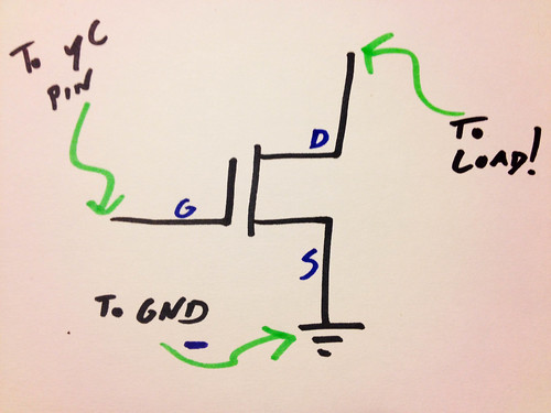
The missing piece, here, is what the *other* end of the speaker is connected to. If one side is connected to drain -- the other side of your speaker should be connected to power. There are a variety of ingenious analogies that explain the way in which a MOSFET Works--controlling a valve, opening and closing a dam--but the more lucid ones escape me now. At any rate, suffice it to say, it allows the relative *weak* microcontroller signal to control a much more powerful flow of current directly from the battery. Which naturally enough, makes it a bit more of a ruckus.
[-###-]{+##+} <a id="helpful-information"></a>Helpful Links & So Forth
- [Copper Circuits Tutorial](http://hlt.media.mit.edu/?p=2505)
[Jie Qi](http://technolojie.com/category/featured-projects/) has put up some useful information about making circuits using copper tape on the High-Low Tech [website](http://hlt.media.mit.edu/?p=2505). There's also good information about the orientation of surface-amount LEDs--which can be tricky to work with!
@@ -157,3 +159,12 @@ A really nice collection of elegant folded designs. Incorporating power into pap
- <a id="datasheet"></a>[ATTiny Datasheet](http://www.atmel.com/Images/Atmel-2586-AVR-8-bit-Microcontroller-ATtiny25-ATtiny45-ATtiny85_Datasheet.pdf)
This is not really that useful for our purposes here--a hundred-odd pages of technical specifications. But it's interesting if you want to delve deeper into how people actually _understand_ these things. And the pin diagram is on the second page.
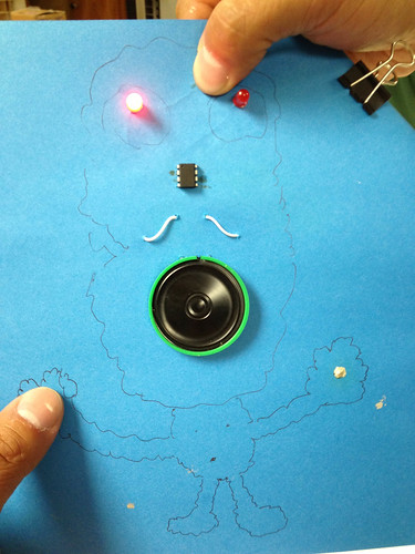
{+## <a id="it-happened"></a>It Happened+}
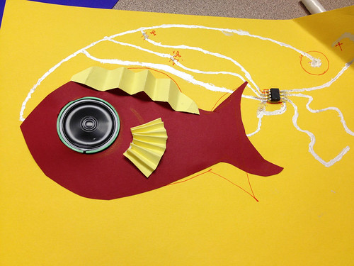
{+April 6 & 7 has come and gone, and people put together many lovely things. Here's a handful:+}
{+{{ macros.render_figure('<a href="http://www.flickr.com/photos/samjacoby/8632165003/" title="Drawing the Electric Synth by s_jacoby, on Flickr"><img src="http://farm9.staticflickr.com/8386/8632165003_c487323eef.jpg" width="375" height="500" alt="Drawing the Electric Synth"></a>',"") }}+}
{+{{ macros.render_figure('<a href="http://www.flickr.com/photos/samjacoby/8633287594/" title="Drawing the Electric Synth by s_jacoby, on Flickr"><img src="http://farm9.staticflickr.com/8107/8633287594_fd4a18aca1.jpg" width="375" height="500" alt="Drawing the Electric Synth"></a>',"") }}+}
{+{{ macros.render_figure('<a href="http://www.flickr.com/photos/samjacoby/8633277890/" title="Drawing the Electric Synth by s_jacoby, on Flickr"><img src="http://farm9.staticflickr.com/8246/8633277890_e6503a9163.jpg" width="500" height="375" alt="Drawing the Electric Synth"></a>',"") }}+}
{+{{ macros.render_figure('<a href="http://www.flickr.com/photos/samjacoby/8632169749/" title="Drawing the Electric Synth by s_jacoby, on Flickr"><img src="http://farm9.staticflickr.com/8522/8632169749_690ba4c5d1.jpg" width="500" height="375" alt="Drawing the Electric Synth"></a>',"") }}+}
{+{{ macros.render_figure('<a href="http://www.flickr.com/photos/samjacoby/8633278348/" title="Drawing the Electric Synth by s_jacoby, on Flickr"><img src="http://farm9.staticflickr.com/8545/8633278348_eb150f37ff.jpg" width="375" height="500" alt="Drawing the Electric Synth"></a>',"") }}+}
{+{{ macros.render_figure('<a href="http://www.flickr.com/photos/samjacoby/8633275918/" title="Drawing the Electric Synth by s_jacoby, on Flickr"><img src="http://farm9.staticflickr.com/8243/8633275918_19d004bbd0.jpg" width="500" height="375" alt="Drawing the Electric Synth"></a>',"") }}+}
2013-04-08 22:55:18 : Adding information on MOSFET.
»
Find fcbdef52f43eed34f4e131400df6f3de68dc8516 on GitHub.
Adding information on MOSFET.
- [Paper Speakers](#paper-speakers)
- [TinyProgrammer](#tinyprogrammer)
- [TinySynth](#tinysynth)
{+- [Adding Amplification with a Mosfet](#mosfet)+}
- [Battery Holder](#battery-holder)
- [Helpful Links](#helpful-information)
## <a id="surveys"></a>Surveys
For our ongoing research at [High-Low Tech](http://hlt.media.mit.edu) and my own thesis, there is a pre-and-post workshop survey that should be filled out. There'll be paper copies available, but filling it out online is quicker and easier!
- [Pre-Workshop [-Survey](https://www.surveymonkey.com/s/YVNDW5F)-]{+Survey](#)+}
- [Post-Workshop [-Survey](https://www.surveymonkey.com/s/YVFN38D)-]{+Survey](#)+}
If you've happened to stumble on this survey and *won't* be attending the workshop, make my life a little easier and don't fill it out!
@@ -77,7 +78,7 @@ To get started with it on your computer, you'll need (a) to have the Arduino IDE
- [TinyProgrammer Tutorial](http://hlt.media.mit.edu/?p=1695)
## <a id="tinysynth"></a>TinySynth
The TinySynth is a [-simple circuit-]{+program loaded onto an ATTiny45/85+} that [-used-]{+uses+} an eight-bit microcontroller to make sounds. We'll need:
- TinyProgrammer
- ATTiny45/85
@@ -103,7 +104,9 @@ While we're programming the chip, we can test some of its functions -- but ultim
{{ macros.render_figure('<a href="http://www.flickr.com/photos/samjacoby/8623874872/" title="IMG_4304 by s_jacoby, on Flickr"><img src="http://farm9.staticflickr.com/8256/8623874872_e352d6b6f1.jpg" width="500" height="375" alt="IMG_4304"></a>', "Your circuit doesn't need to look like this at all. These are just the connections.") }}
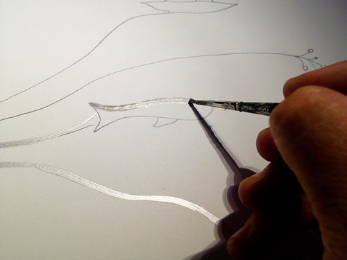
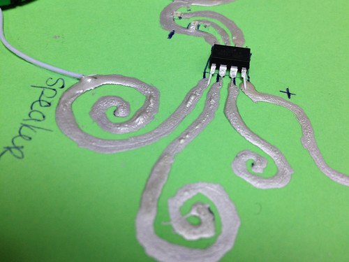
Applying silver ink can be difficult. Go slow. With attention and care, you can draw fine, well-controlled traces.
[-Unless of course, you don't want to, in which case, go nuts!-]{+Preparing your microcontroller to work on a paper surface also requires some attention. Dave Mellis has put up some good, relevant guidlines here: [Micocontroller Circuit with Copper Tape](http://hlt.media.mit.edu/?p=1653).+}
{{ macros.render_figure('<a href="http://www.flickr.com/photos/samjacoby/7976725337/" title="Electric Narratives by s_jacoby, on Flickr"><img src="http://farm9.staticflickr.com/8440/7976725337_297dd84636.jpg" width="500" height="375" alt="Electric Narratives"></a>', "Painting with conductive silver ink.") }}
@@ -126,6 +129,21 @@ Using conductive ink, paint over the fold as shown in the black rectangles below
Fasten the folded over corner down over the battery with a binder clip.
{{ macros.render_figure('<a href="http://www.flickr.com/photos/samjacoby/8622772695/" title="IMG_4314 by s_jacoby, on Flickr"><img src="http://farm9.staticflickr.com/8257/8622772695_aea218f794.jpg" width="500" height="375" alt="IMG_4314"></a>', '') }}
{+## <a id="mosfet"></a>Adding Amplification with a MOSFET+}
{+- N-Channel MOSFET ([DigiKey](http://www.digikey.com/product-detail/en/NTD5867NL-1G/NTD5867NL-1GOS-ND/2401422?cur=USD))+}
{+Once you've made your circuit, you'll probably notice that it's not overwhelmingly loud. That's because we're driving the speaker with one of the pins of the microcontroller, which really isn't great for that sort of thing. According to the [datasheet](#datasheet), the ATTiny can source about 20 milliamps, which isn't all that much. Using a MOSFET, we can drive a great deal more current through our speaker--and theoretically at least--make it louder. +}
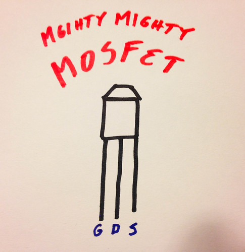
{+Here's my crude schematic of the mosfet that we'll be using. It has a particularly low threshold-voltage, which means it works well with the low-voltage coin-cell batteries. It's an [N-channel MOSFET](http://en.wikipedia.org/wiki/Mosfet), which is very important, though why, I could not say. +}
{+{{ macros.render_figure('<a href="http://www.flickr.com/photos/samjacoby/8623875122/" title="IMG_4305 by s_jacoby, on Flickr"><img src="http://farm9.staticflickr.com/8530/8623875122_1e2968ca26.jpg" width="485" height="500" alt="IMG_4305"></a>', "G: Gate, D: Drain, S: source") }}+}
{+Figuring out just how the "FET"--as such things are sometimes called--is hooked up into the circuit is trickier than it should be, at least for me. We're interested in the gate, drain, and source. The gate is what we'll connect to our microcontroller. The source, we'll connect straight to ground. And the drain, we'll connect to one end of our speaker. The diagram below gives about half the answer. +}
{+{{ macros.render_figure('<a href="http://www.flickr.com/photos/samjacoby/8623875340/" title="IMG_4307 by s_jacoby, on Flickr"><img src="http://farm9.staticflickr.com/8534/8623875340_6202ddab72.jpg" width="500" height="375" alt="IMG_4307"></a>', "") }}+}
{+The missing piece, here, is what the *other* end of the speaker is connected to. If one side is connected to drain -- the other side of your speaker should be connected to power. There are a variety of ingenious analogies that explain the way in which a MOSFET Works--controlling a valve, opening and closing a dam--but the more lucid ones escape me now. At any rate, suffice it to say, it allows the relative *weak* microcontroller signal to control a much more powerful flow of current directly from the battery. Which naturally enough, makes it a bit more of a ruckus.+}
### <a id="helpful-information"></a>Helpful Links & So Forth
- [Copper Circuits Tutorial](http://hlt.media.mit.edu/?p=2505)
@@ -136,6 +154,6 @@ Fasten the folded over corner down over the battery with a binder clip.
A really nice collection of elegant folded designs. Incorporating power into paper electronic projects has long been tricky, and these are some nice solutions. We've long-used a binder clip and a coin-cell battery, which works pretty well too.
- [-[ATTiny-]{+<a id="datasheet"></a>[ATTiny+} Datasheet](http://www.atmel.com/Images/Atmel-2586-AVR-8-bit-Microcontroller-ATtiny25-ATtiny45-ATtiny85_Datasheet.pdf)
This is not really that useful for our purposes here--a hundred-odd pages of technical specifications. But it's interesting if you want to delve deeper into how people actually _understand_ these things. And the pin diagram is on the second page.
2013-04-06 21:46:50 : Updating survey links for the next. day.
»
Find fc9eb46ad48230dfb7cb8ce4f298c4e7752f194d on GitHub.
Updating survey links for the next. day.
## <a id="surveys"></a>Surveys
For our ongoing research at [High-Low Tech](http://hlt.media.mit.edu) and my own thesis, there is a pre-and-post workshop survey that should be filled out. There'll be paper copies available, but filling it out online is quicker and easier!
- [Pre-Workshop [-Survey](https://www.surveymonkey.com/s/HXQLFJ2)-]{+Survey](https://www.surveymonkey.com/s/YVNDW5F)+}
- [Post-Workshop [-Survey](https://www.surveymonkey.com/s/99T53TQ)-]{+Survey](https://www.surveymonkey.com/s/YVFN38D)+}
If you've happened to stumble on this survey and *won't* be attending the workshop, make my life a little easier and don't fill it out!
@@ -49,7 +49,7 @@ If you've happened to stumble on this survey and *won't* be attending the worksh
I've written up the basics, gleaned from many-a-resource, here:
- [Speakers [-Paperish](http://localhost:8080/posts/2013/4/1/speaker-paperish)-]{+Paperish](http://samjacoby.com/posts/2013/4/1/speaker-paperish)+}
[Hannah Perner-Wilson](http://plusea.at) is a one-person armada. She has done a variety of gorgeous pieces:
@@ -103,7 +103,13 @@ While we're programming the chip, we can test some of its functions -- but ultim
{{ macros.render_figure('<a href="http://www.flickr.com/photos/samjacoby/8623874872/" title="IMG_4304 by s_jacoby, on Flickr"><img src="http://farm9.staticflickr.com/8256/8623874872_e352d6b6f1.jpg" width="500" height="375" alt="IMG_4304"></a>', "Your circuit doesn't need to look like this at all. These are just the connections.") }}
{+Applying silver ink can be difficult. Go slow. With attention and care, you can draw fine, well-controlled traces. Unless of course, you don't want to, in which case, go nuts!+}
{+{{ macros.render_figure('<a href="http://www.flickr.com/photos/samjacoby/7976725337/" title="Electric Narratives by s_jacoby, on Flickr"><img src="http://farm9.staticflickr.com/8440/7976725337_297dd84636.jpg" width="500" height="375" alt="Electric Narratives"></a>', "Painting with conductive silver ink.") }}+}
{+**Note:** The conductive silver ink we'll be using dries fairly slowly and was designed to be heat-dried at a specific temperature. A regular toaster oven will do the job. We've supplied some hot-air stations and heateriziers that should work just as well. When working with microcontrollers, as we are, you need to be sensitive to the resistance of each line, because the microcontroller expects a very specific range of voltages on its pins.+}
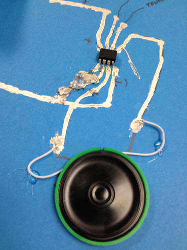
Here's [-an-]{+a complete+} example with a big ol' gramophone cone sticking out. This uses a painted silver speaker (instead of a wound-wire speaker), which works, but without amplification, is very quiet!
{{ macros.render_figure('<a href="http://www.flickr.com/photos/samjacoby/8465566076/" title="Capactive touch button by s_jacoby, on Flickr"><img src="http://farm9.staticflickr.com/8233/8465566076_f70ec81291.jpg" width="500" height="375" alt="Capactive touch button"></a>', "Speakers need to be coiled in a single direction--so on the back of this sheet, there's a straight line leaving the center.") }}
2013-04-06 02:17:21 : Onward, Onward.
»
Find 26bd9eb66625f7896a89b3a66690bd4653df5e04 on GitHub.
Onward, Onward.
- [TinyProgrammer](#tinyprogrammer)
- [TinySynth](#tinysynth)
- [Battery Holder](#battery-holder)
- [Helpful [-Information](#helpful-information)-]{+Links](#helpful-information)+}

## <a id="surveys"></a>Surveys
For our ongoing research at [High-Low Tech](http://hlt.media.mit.edu) and my own thesis, there is a pre-and-post workshop survey that should be filled out. There'll be paper copies available, but filling it out online is quicker and easier!

- [Pre-Workshop Survey](https://www.surveymonkey.com/s/HXQLFJ2)
- [Post-Workshop [-Survey](http://#)-]{+Survey](https://www.surveymonkey.com/s/99T53TQ)+}

If you've happened to stumble on this survey and *won't* be attending the workshop, make my life a little easier and don't fill it out!

@@ -70,7 +70,7 @@ I put together a simple template, that guides you on how to make the design show

- TinyProgrammer ([SparkFun](https://www.sparkfun.com/products/11460))

The TinyProgrammer is a sweet little tool that vastly simplifies the programming of Atmel's ATTiny45/85 microcontrollers. The ATTiny can do just about everything an Arduino can do (Atmel makes the ATmega168/32U4), but are much cheaper, smaller, and more easily embedded. If you want to make twenty of something, it's a lot easier to get your hands on 20 [-ATTiny's-]{+ATTinys+} (they're [$.95]() on SparkFun) than 20 Arduinos. [David Mellis](http://media.mit.edu/~mellis) designed this one. Or actually, he designed one, and SparkFun redesigned it to make it way better.

To get started with it on your computer, you'll need (a) to have the Arduino IDE installed (get it [here](http://arduino.cc/en/Main/Software) if you haven't already) and (b) have ATTiny installed (it doesn't come with the normal download). While the ATTiny is an Atmel chip (like the chips that power the Arduino), Arduino doesn't come with support for the ATTiny family out-of-the-box, so you'll have to follow the tutorial below to add ATTiny Support. Hopefully this'll change at some point.

@@ -121,10 +121,10 @@ Fasten the folded over corner down over the battery with a binder clip.
{{ macros.render_figure('<a href="http://www.flickr.com/photos/samjacoby/8622772695/" title="IMG_4314 by s_jacoby, on Flickr"><img src="http://farm9.staticflickr.com/8257/8622772695_aea218f794.jpg" width="500" height="375" alt="IMG_4314"></a>', '') }}


{+### <a id="helpful-information"></a>Helpful Links & So Forth+}
{+- [Copper Circuits Tutorial](http://hlt.media.mit.edu/?p=2505)+}

[-### <a id="helpful-information"></a>Helpful Information-][Jie Qi](http://technolojie.com/category/featured-projects/) has put up some useful information about making circuits using copper tape on the High-Low Tech [website](http://hlt.media.mit.edu/?p=2505). {+There's also good information about the orientation of surface-amount LEDs--which can be tricky to work with!+}

- [Bare Conductive's Paper Battery Holder](http://www.bareconductive.com/paper-battery-holders)
2013-04-06 01:36:07 : Finalizing (most) details.
»
Find a98569e4ef699112a415cd670d56c85e6c174f9f on GitHub.
Finalizing (most) details.
---
*This is a compendium of resources assembled for a workshop over the weekend of April 6 and 7 at SparkFun Electronics in Boulder, Colorado.*
## Workshop Description
We’ll explore conductive inks and other materials to create unique, interactive musical instruments. Learn the basics of embedded microcontroller programming and circuit design, while crafting miniature synthesizers using a combination of electronics, programming, and art materials. For those interested, we can delve into the mysteries of FM sound generation and work on creating structed, pictorial representations of sound. No experience necessary—but you’ve got to love crafts, drawing, sound, and learning new ways of making electronics.
## [-Surveys-]{+Contents+}
{+- [Surveys](#surveys)+}
{+- [Schedule](#schedule)+}
{+- [Paper Speakers](#paper-speakers)+}
{+- [TinyProgrammer](#tinyprogrammer)+}
{+- [TinySynth](#tinysynth)+}
{+- [Battery Holder](#battery-holder)+}
{+- [Helpful Information](#helpful-information)+}
{+## <a id="surveys"></a>Surveys+}
For our ongoing research at [High-Low Tech](http://hlt.media.mit.edu) and my own thesis, there is a pre-and-post workshop survey that should be filled out. There'll be paper copies available, but filling it out online is quicker and easier!
- [Pre-Workshop Survey](https://www.surveymonkey.com/s/HXQLFJ2)
@@ -16,7 +28,7 @@ For our ongoing research at [High-Low Tech](http://hlt.media.mit.edu) and my own
If you've happened to stumble on this survey and *won't* be attending the workshop, make my life a little easier and don't fill it out!
## [-Schedule (tentative)-]{+<a id="schedule"></a>Schedule (theoretically)+}
<table>
<tr><td>**9:00** </td><td>Surveys!</td></tr>
<tr><td>**9:15** </td><td>Introductions (me, mostly)</td></tr>
@@ -29,10 +41,11 @@ If you've happened to stumble on this survey and *won't* be attending the worksh
<tr><td>**1:15** </td><td>Programming TinySynth </td></tr>
<tr><td>**1:30** </td><td>Code overview</td></tr>
<tr><td>**1:45** </td><td>Make some Synths!</td></tr>
{+<tr><td>**2:10** </td><td> <span style="color: red">Break</span></td></tr>+}
<tr><td>**4:45** </td><td>Fill out post-workshop survey</td></tr>
</table>
## [-Paper-]{+<a id="paper-speakers"></a>Paper+} Speakers
I've written up the basics, gleaned from many-a-resource, here:
@@ -50,38 +63,69 @@ I've written up the basics, gleaned from many-a-resource, here:
- [Printed + Handmade Headphones](http://www.karich.cl/?p=601)
- [Dollar Bill Ghetto Blaster](http://www.karich.cl/?p=172)
{+### <a id="templates"></a> Templates+}
{+I put together a simple template, that guides you on how to make the design shown here, [Speakers Paperish](http://localhost:8080/posts/2013/4/1/speaker-paperish). It's just a rough guideline, but can give you some ideas. Download the the PDF here: [Business Card Paper Speaker Template](/files/paper-speaker-template.pdf).+}
{+### <a id="tinyprogrammer"></a> TinyProgrammer+}
{+- TinyProgrammer ([SparkFun](https://www.sparkfun.com/products/11460))+}
{+The TinyProgrammer is a sweet little tool that vastly simplifies the programming of Atmel's ATTiny45/85 microcontrollers. The ATTiny can do just about everything an Arduino can do (Atmel makes the ATmega168/32U4), but are much cheaper, smaller, and more easily embedded. If you want to make twenty of something, it's a lot easier to get your hands on 20 ATTiny's (they're [$.95]() on SparkFun) than 20 Arduinos. [David Mellis](http://media.mit.edu/~mellis) designed this one. Or actually, he designed one, and SparkFun redesigned it to make it way better. +}
{+To get started with it on your computer, you'll need (a) to have the Arduino IDE installed (get it [here](http://arduino.cc/en/Main/Software) if you haven't already) and (b) have ATTiny installed (it doesn't come with the normal download). While the ATTiny is an Atmel chip (like the chips that power the Arduino), Arduino doesn't come with support for the ATTiny family out-of-the-box, so you'll have to follow the tutorial below to add ATTiny Support. Hopefully this'll change at some point. +}
{+- [TinyProgrammer Tutorial](http://hlt.media.mit.edu/?p=1695)+}
## {+<a id="tinysynth"></a>TinySynth+}
{+The+} TinySynth {+is a simple circuit that used an eight-bit microcontroller to make sounds. We'll need:+}
[-The TinySynth is an eight-bit microcontroller that makes sounds. We'll need:-]
- TinyProgrammer
- [-Tiny45V-]{+ATTiny45/85+}
- Coin Cell
- [Paper Speaker](/posts/2013/4/1/speaker-paperish/)
- Conductive Ink
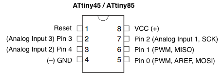
Getting up and playing with the Tiny is simple enough. Most of the default Arduino sketches work with the [-ATTIny-]{+ATTiny+} outt've of the box. Some things will have to be tweaked, though, as the default Arduino pins don't necessarily map to anything useful on the Tiny--pin 13, which by default is connected to an LED on an Arduino board doesn't go anywhere on a Tiny:
{{ macros.render_figure('<img class="no-border" src="/media/img/attiny45_85pinout.png"/>', "Arduino-compatible pinout for Tiny45 (image courtesy of [David Mellis](http://hlt.media.mit.edu/?p=1695)).") }}
The program that we'll be loading onto our Tiny's is a basic sound generation library I've written. You can peruse the source over on [GitHub](https://github.com/samjacoby/tinysynth), and down a .zip of the necessary files here: [zip archive](https://github.com/samjacoby/tinysynth/archive/master.zip).
To use,[-simply-] unzip the folder and open the "tinysynth.ino" file (you need to have Arduino installed).
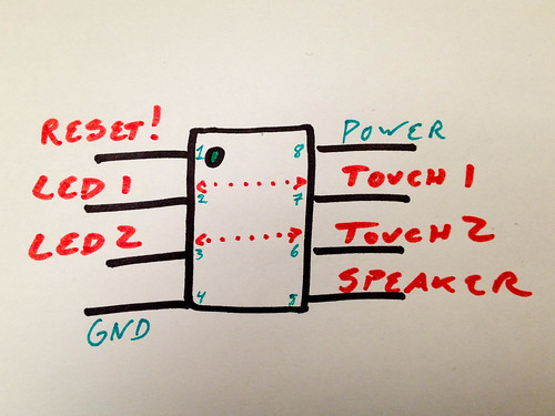
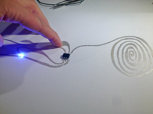
TinySynth has been preconfigured to have two touch-sensitive capacitive sensors and two LEDs, as well as a speaker output. See below:
{{ macros.render_figure('<a href="http://www.flickr.com/photos/samjacoby/8616341819/" title="IMG_4275 by s_jacoby, on Flickr"><img src="http://farm9.staticflickr.com/8542/8616341819_38f4b4a9c7.jpg" width="500" height="375" alt="IMG_4275"></a>', "`TOUCH1` triggers `LED1`, `TOUCH2` triggers `LED2`") }}
The `RESET` pin is only used while the chip is being programmed. We could disable it, but it means that you'd need some special hardware to ever program the chip again. `POWER` and `GND`, naturally enough, are connected to the positive and negative terminals of your power supply--in our case, a coin-cell [-battery.-]{+battery or what-have-you.+}
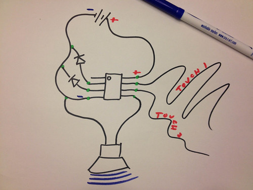
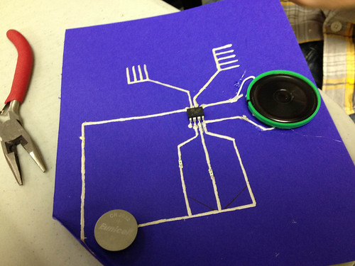
[-### TinyProgrammer-]{+While we're programming the chip, we can test some of its functions -- but ultimately, we're going to making fancy-pants circuits outt've of conductive ink. Below is a rough schematic of what the circuit looks like. The various symbols correspond to different components: batteries, LEDs, and so forth. Which is which? You decide!+}
[-- TinyProgrammer ([SparkFun](https://www.sparkfun.com/products/11460))-]{+{{ macros.render_figure('<a href="http://www.flickr.com/photos/samjacoby/8623874872/" title="IMG_4304 by s_jacoby, on Flickr"><img src="http://farm9.staticflickr.com/8256/8623874872_e352d6b6f1.jpg" width="500" height="375" alt="IMG_4304"></a>', "Your circuit doesn't need to look like this at all. These are just the connections.") }}+}
[-The TinyProgrammer is a sweet little tool that vastly simplifies the programming of Atmel's ATTiny45/85 microcontrollers. The ATTiny can do just about everything-]{+Here's+} an [-Arduino can do (Atmel makes the ATmega168/32U4), but are much cheaper, smaller, and more easily embedded. If you want to make twenty-]{+example with a big ol' gramophone cone sticking out. This uses a painted silver speaker (instead+} of[-something, it's-] a [-lot easier to get your hands on 20 ATTiny's than 20 Arduinos. [David Mellis](http://media.mit.edu/~mellis) designed this one.-]{+wound-wire speaker), which works, but without amplification, is very quiet!+}
[-- [TinyProgrammer Tutorial](http://hlt.media.mit.edu/?p=1695)-]{+{{ macros.render_figure('<a href="http://www.flickr.com/photos/samjacoby/8465566076/" title="Capactive touch button by s_jacoby, on Flickr"><img src="http://farm9.staticflickr.com/8233/8465566076_f70ec81291.jpg" width="500" height="375" alt="Capactive touch button"></a>', "Speakers need to be coiled in a single direction--so on the back of this sheet, there's a straight line leaving the center.") }}+}
{+## <a id="battery-holder"></a>Battery Holders+}
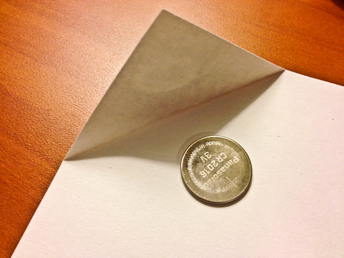
{+Integrating "hard" components, like batteries and microcontrollers, with "soft" materials, like paper and textiles, is always difficult. Here's one way of creating battery a battery holder for a coin-cell battery, using the corner of a sheet of paper and a binder clip. +}
{+Fold over the corner of a sheet of paper. It should completely and easily cover the battery.+}
{+{{ macros.render_figure('<a href="http://www.flickr.com/photos/samjacoby/8623875732/" title="IMG_4311 by s_jacoby, on Flickr"><img src="http://farm9.staticflickr.com/8522/8623875732_a2e2d02511.jpg" width="500" height="375" alt="IMG_4311"></a>', '') }}+}
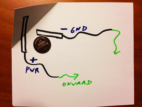
{+Using conductive ink, paint over the fold as shown in the black rectangles below. Because conductive paint doesn't crease well, it can sometimes be a good idea to replace those portions of your circuit with short lengths of copper tape ([SparkFun](https://www.sparkfun.com/products/10561). The configuration has to be relatively precise, because you don't want to short the battery. Position it with the (+) side up.+}
{+{{ macros.render_figure('<a href="http://www.flickr.com/photos/samjacoby/8623875978/" title="IMG_4313 by s_jacoby, on Flickr"><img src="http://farm9.staticflickr.com/8406/8623875978_d86d1c659b.jpg" width="500" height="375" alt="IMG_4313"></a>','') }}+}
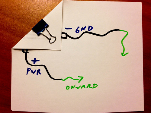
{+Fasten the folded over corner down over the battery with a binder clip.+}
{+{{ macros.render_figure('<a href="http://www.flickr.com/photos/samjacoby/8622772695/" title="IMG_4314 by s_jacoby, on Flickr"><img src="http://farm9.staticflickr.com/8257/8622772695_aea218f794.jpg" width="500" height="375" alt="IMG_4314"></a>', '') }}+}
{+### <a id="helpful-information"></a>Helpful Information+}
{+[Jie Qi](http://technolojie.com/category/featured-projects/) has put up some useful information about making circuits using copper tape on the High-Low Tech [website](http://hlt.media.mit.edu/?p=2505).+}
[-### Helpful Information-]
- [Bare Conductive's Paper Battery Holder](http://www.bareconductive.com/paper-battery-holders)
A really nice collection of elegant folded designs. Incorporating power into paper electronic projects has long been tricky, and these are some nice solutions. We've long-used a binder clip and a coin-cell battery, which works pretty well too.
2013-04-04 20:28:41 : Adding (tenative) schedule.
»
Find 07fc32596cb6adc9ca78816bd9f8e133e544eb61 on GitHub.
Adding (tenative) schedule.
## Surveys
For our ongoing research at [High-Low Tech](http://hlt.media.mit.edu) and my own thesis, there is a pre-and-post workshop survey that should be filled out. There'll be paper copies available, but filling it out online is quicker and easier!

- [Pre-Workshop [-Survey](http://#)-]{+Survey](https://www.surveymonkey.com/s/HXQLFJ2)+}
- [Post-Workshop Survey](http://#)

{+If you've happened to stumble on this survey and *won't* be attending the workshop, make my life a little easier and don't fill it out! +}

{+## Schedule (tentative)+}
{+<table>+}
{+    <tr><td>**9:00** </td><td>Surveys!</td></tr>+}
{+<tr><td>**9:15** </td><td>Introductions (me, mostly)</td></tr>+}
{+<tr><td>**9:30** </td><td>How-to-make a Paper Speaker </td></tr>+}
{+<tr><td>**10:20** </td><td> <span style="color: red">Break</span></td></tr>+}
{+<tr><td>**10:30** </td><td>Making circuits with Conductive Ink</td></tr>+}
{+<tr><td>**11:30** </td><td>A brief introduction to the ATTiny + TinyProgrammer (this might be ambitious)</td></tr>+}
{+<tr><td>**12:00** </td><td><span style="color:red">Lunch & Arduino-debugging</span></td></tr>+}
{+<tr><td>**1:00** </td><td>Programming Blink. It's a miracle!</td></tr>+}
{+<tr><td>**1:15** </td><td>Programming TinySynth </td></tr>+}
{+<tr><td>**1:30** </td><td>Code overview</td></tr>+}
{+<tr><td>**1:45** </td><td>Make some Synths!</td></tr>+}
{+<tr><td>**4:45** </td><td>Fill out post-workshop survey</td></tr>+}
{+</table>+}

## Paper Speakers

I've written up the basics, gleaned from many-a-resource, here:
2013-04-04 15:52:57 : Adding Karich's lovely projects.
»
Find b868acb673c06fcb38767fa8ca5b8294cc625aa3 on GitHub.
Adding Karich's lovely projects.
[Marcelo Coelho](http://www.cmarcelo.com/#/pulp-based-computing/) put together some particularly striking, insprirational examples, if a bit more involved than what we'll be making.

{+[jckarich](http://www.karich.cl) has a number of gorgeous projects (some done right at home, in the [MIT Media Lab](http://media.mit.edu)):+}

{+- [Printed + Handmade Headphones](http://www.karich.cl/?p=601)+}
{+- [Dollar Bill Ghetto Blaster](http://www.karich.cl/?p=172)+}

## TinySynth

The TinySynth is an eight-bit microcontroller that makes sounds. We'll need:
2013-04-04 11:59:20 : Adding details and links. Survey links are dead.
»
Find c15f3eaa68b96b63cdea85ebf982207e56b3219c on GitHub.
Adding details and links. Survey links are dead.
---
title: Drawing the Electric Synth
summary: A workshop at SparkFun [-Electroncs-]{+Electronics.+}
date: 2013-04-02 12:19:50
---
*This is a compendium of resources assembled for a workshop over the weekend of April 6 and 7 at SparkFun Electronics in Boulder, Colorado.*

[-###-]{+##+} Workshop Description
We’ll explore conductive inks and other materials to create unique, interactive musical instruments. Learn the basics of embedded microcontroller programming and circuit design, while crafting miniature synthesizers using a combination of electronics, programming, and art materials. For those interested, we can delve into the mysteries of FM sound generation and work on creating structed, pictorial representations of sound. No experience necessary—but you’ve got to love crafts, drawing, sound, and learning new ways of making electronics.

[-###-]{+##+} Surveys
For our ongoing research at [High-Low Tech](http://hlt.media.mit.edu) and my own thesis, there is a pre-and-post workshop survey that should be filled [-out:-]{+out. There'll be paper copies available, but filling it out online is quicker and easier!+}

- [Pre-Workshop Survey](http://#)
- [Post-Workshop Survey](http://#)

[-### TinyProgrammer-]{+## Paper Speakers+}

[-- TinyProgrammer ([SparkFun](https://www.sparkfun.com/products/11460))-]{+I've written up the basics, gleaned from many-a-resource, here:+}

[-The TinyProgrammer is a sweet little tool that vastly simplifies the programming of Atmel's ATTiny45/85 microcontrollers. The 'tinys', as they're affectionately called, can do just about everything an Arduino can do (Atmel makes the ATmega168/32U4), but are much cheaper, smaller, and for our purposes--much more easily embedded. [David Mellis](http://media.mit.edu/~mellis) designed this one.-]{+- [Speakers Paperish](http://localhost:8080/posts/2013/4/1/speaker-paperish)+}

[-- [TinyProgrammer Tutorial](http://hlt.media.mit.edu/?p=1695)-]{+[Hannah Perner-Wilson](http://plusea.at) is a one-person armada. She has done a variety of gorgeous pieces:+}

[-### Paper Speakers-]{+- [Paper Speaker Tutorial](http://hlt.media.mit.edu/?p=1372) at High-Low Tech. +}
{+- [Sea-shell Headphones](http://www.plusea.at/?p=4596)+}

[-I've written up the basics, gleaned from many-a-resource, in-]{+[Marcelo Coelho](http://www.cmarcelo.com/#/pulp-based-computing/) put together some particularly striking, insprirational examples, if+} a [-post, here:-]{+bit more involved than what we'll be making.+}

[-- [Speakers Paperish](http://localhost:8080/posts/2013/4/1/speaker-paperish)-]{+## TinySynth+}

[-[Hannah Perner-Wilson](http://plusea.at), as always,-]{+The TinySynth+} is [-a one-woman army. She has done a variety of gorgeous pieces:-]{+an eight-bit microcontroller that makes sounds. We'll need:+}
{+- TinyProgrammer+}
{+- Tiny45V+}
{+- Coin Cell+}
{+- [Paper Speaker](/posts/2013/4/1/speaker-paperish/)+}
{+- Conductive Ink+}

[-- [Paper Speaker Tutorial](http://hlt.media.mit.edu/?p=1372)-]{+Getting up and playing with the Tiny is simple enough. Most of the default Arduino sketches work with the ATTIny outt've of the box. Some things will have to be tweaked, though, as the default Arduino pins don't necessarily map to anything useful+} on the [-High-Low Tech Site -]
[-- [Sea-shell Headphones](http://www.plusea.at/?p=4596)-]{+Tiny--pin 13, which by default is connected to an LED on an Arduino board doesn't go anywhere on a Tiny:+}

[-[Marcelo Coelho](http://www.cmarcelo.com/#/pulp-based-computing/) put together some particularly striking, insprirational examples, if a bit more involved than what-]{+{{ macros.render_figure('<img class="no-border" src="/media/img/attiny45_85pinout.png"/>', "Arduino-compatible pinout for Tiny45 (image courtesy of [David Mellis](http://hlt.media.mit.edu/?p=1695)).") }} +}

{+The program that+} we'll be [-making.-]{+loading onto our Tiny's is a basic sound generation library I've written. You can peruse the source over on [GitHub](https://github.com/samjacoby/tinysynth), and down a .zip of the necessary files here: [zip archive](https://github.com/samjacoby/tinysynth/archive/master.zip).  +}

{+To use, simply unzip the folder and open the "tinysynth.ino" file (you need to have Arduino installed).+}

[-## Tiny Synth-]{+TinySynth has been preconfigured to have two touch-sensitive capacitive sensors and two LEDs, as well as a speaker output. See below:+}

{+{{ macros.render_figure('<a href="http://www.flickr.com/photos/samjacoby/8616341819/" title="IMG_4275 by s_jacoby, on Flickr"><img src="http://farm9.staticflickr.com/8542/8616341819_38f4b4a9c7.jpg" width="500" height="375" alt="IMG_4275"></a>', "`TOUCH1` triggers `LED1`, `TOUCH2` triggers `LED2`") }}+}

{+The `RESET` pin is only used while the chip is being programmed. We could disable it, but it means that you'd need some special hardware to ever program the chip again. `POWER` and `GND`, naturally enough, are connected to the positive and negative terminals of your power supply--in our case, a coin-cell battery.  +}

{+### TinyProgrammer+}

{+- TinyProgrammer ([SparkFun](https://www.sparkfun.com/products/11460))+}

{+The TinyProgrammer is a sweet little tool that vastly simplifies the programming of Atmel's ATTiny45/85 microcontrollers. The ATTiny can do just about everything an Arduino can do (Atmel makes the ATmega168/32U4), but are much cheaper, smaller, and more easily embedded. If you want to make twenty of something, it's a lot easier to get your hands on 20 ATTiny's than 20 Arduinos. [David Mellis](http://media.mit.edu/~mellis) designed this one. +}

{+- [TinyProgrammer Tutorial](http://hlt.media.mit.edu/?p=1695)+}

### Helpful Information
- [Bare Conductive's Paper Battery Holder](http://www.bareconductive.com/paper-battery-holders)
@@ -44,6 +65,4 @@ A really nice collection of elegant folded designs. Incorporating power into pap

- [ATTiny Datasheet](http://www.atmel.com/Images/Atmel-2586-AVR-8-bit-Microcontroller-ATtiny25-ATtiny45-ATtiny85_Datasheet.pdf)

This is not really that [-useful--a-]{+useful for our purposes here--a+} hundred-odd pages of technical specifications. But it's interesting if you want to delve deeper into how people actually _understand_ these things. And the pin diagram is on the second page.
2013-04-03 10:29:07 : Come ye, to the internet, and learneth.
»
Find 3b9b1c6dc25e8185d4b9a5222276d70da2be92d3 on GitHub.
Come ye, to the internet, and learneth.
@@ -0,0 +1,49 @@
{+---+}
{+title: Drawing the Electric Synth+}
{+summary: A workshop at SparkFun Electroncs+}
{+date: 2013-04-02 12:19:50+}
{+---+}
{+*This is a compendium of resources assembled for a workshop over the weekend of April 6 and 7 at SparkFun Electronics in Boulder, Colorado.*+}

{+### Workshop Description+}
{+We’ll explore conductive inks and other materials to create unique, interactive musical instruments. Learn the basics of embedded microcontroller programming and circuit design, while crafting miniature synthesizers using a combination of electronics, programming, and art materials. For those interested, we can delve into the mysteries of FM sound generation and work on creating structed, pictorial representations of sound. No experience necessary—but you’ve got to love crafts, drawing, sound, and learning new ways of making electronics.+}

{+### Surveys+}
{+For our ongoing research at [High-Low Tech](http://hlt.media.mit.edu) and my own thesis, there is a pre-and-post workshop survey that should be filled out: +}

{+- [Pre-Workshop Survey](http://#)+}
{+- [Post-Workshop Survey](http://#)+}

{+### TinyProgrammer+}

{+- TinyProgrammer ([SparkFun](https://www.sparkfun.com/products/11460))+}

{+The TinyProgrammer is a sweet little tool that vastly simplifies the programming of Atmel's ATTiny45/85 microcontrollers. The 'tinys', as they're affectionately called, can do just about everything an Arduino can do (Atmel makes the ATmega168/32U4), but are much cheaper, smaller, and for our purposes--much more easily embedded. [David Mellis](http://media.mit.edu/~mellis) designed this one. +}

{+- [TinyProgrammer Tutorial](http://hlt.media.mit.edu/?p=1695)+}

{+### Paper Speakers+}

{+I've written up the basics, gleaned from many-a-resource, in a post, here: +}

{+- [Speakers Paperish](http://localhost:8080/posts/2013/4/1/speaker-paperish)+}

{+[Hannah Perner-Wilson](http://plusea.at), as always, is a one-woman army. She has done a variety of gorgeous pieces:+}

{+- [Paper Speaker Tutorial](http://hlt.media.mit.edu/?p=1372) on the High-Low Tech Site +}
{+- [Sea-shell Headphones](http://www.plusea.at/?p=4596)+}

{+[Marcelo Coelho](http://www.cmarcelo.com/#/pulp-based-computing/) put together some particularly striking, insprirational examples, if a bit more involved than what we'll be making.+}

{+## Tiny Synth+}

{+### Helpful Information+}
{+- [Bare Conductive's Paper Battery Holder](http://www.bareconductive.com/paper-battery-holders)+}

{+A really nice collection of elegant folded designs. Incorporating power into paper electronic projects has long been tricky, and these are some nice solutions. We've long-used a binder clip and a coin-cell battery, which works pretty well too.  +}

{+- [ATTiny Datasheet](http://www.atmel.com/Images/Atmel-2586-AVR-8-bit-Microcontroller-ATtiny25-ATtiny45-ATtiny85_Datasheet.pdf) +}

{+This is not really that useful--a hundred-odd pages of technical specifications. But it's interesting if you want to delve deeper into how people actually _understand_ these things. And the pin diagram is on the second page.+}