Paper Sensors
Posted . [Last updated . ]
The idea, here, was to recreate some basic MEMS sensors using paper & conductive ink.
The raw materials. A bit of silver ink—this stuff, from Conductive Compounds, a mysterious organization up in New Hampshire—a brush, and a laser-cut stencil. I designed the circuit in Eagle, though that was just for my own amusement.
The modern scientist.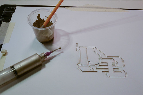
Of course, the “right” way to do it, is to screen-print it, but I am lazy. Dabbed on a bit through the stencil, which I’d tacked down with some spray adhesive.
Worked about half-the-time.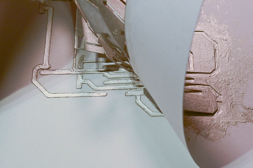
Strain Gauge
This design is based on the work of the George Whitesides Lab, who have done a lot of fine work in paper electronics. Actually, they’ve done most of the work in paper electronics. Pretty good stuff.
Strain gauge, from Paper-based piezoresistive MEMS sensors, Liu et al.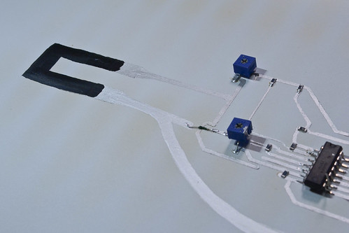
The black stripe is carbon-based ink, which has a far higher resistivity than the silver stuff, and changes resistivity dramatically when flexed. The components are attached with conductive epoxy, which works pretty well. You can speed the drying process along by throwing it in a toaster—you can see the baked lines on this guy. I left it in too long. Worked fine. When cured, the ink goes down to something like 0.3Ω/cm. Not bad.
This is an early test of just the paper gauge. It seems a little lagged, but I think that’s just because I did a bad job syncing the videos—and because of the latency inherent in the flex of the paper.
This package just has four op-amps, each boosting up the signal to a different level. The blue blocks are adjustable potentiometers, to equalize the legs of the Wheatstone Bridge, making the gauge damn sensitive. Op-amp at the heart of the strain-gauge, doing some fine work.

Paper Accelerometer
The accelerometer works on a totally different principle, and a lot of the fanciness isn’t embedded on the page—though there is a transimpedance amplifier, in there, which converts the voltage on one plate into current, allowing for the flexing of the little paper tab to be picked up.
It’s a pretty crude accelerometer and works pretty well when you blow on it too. No word on durability. I’d guess, not very.
Accelerometer. Or anemometer, for that matter.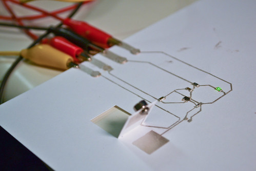
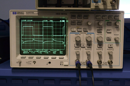
This is what the scope picks up on the other side. The square is wave is being sent out of a microcontroller (an Arduino)—and you can see the inverted signal coming through on the opposing plate. By shaking the accelerometer, the voltage of the induced signal changes—it’s larger when the two plates are closer. A current is only induced when the voltage is changing, though, which is why there are only spikes when the square wave is changing. That gives you a crude metric of motion—hence, the accelerometer. I wouldn’t say it’s all that reliable or repeatable, though. Scope. First row is the transmission wave. Second is the induced (post-amplification) voltage.
Thanks to the ever-generous BDM for helping make this happen.